Robotics fascinates me since it is a technically interdisciplinary field. Building robots means to deal with electrical engineering, mechanics, physics and software. In addition, every robot that interacts with its environment creates a kind of artificial, new life.
A generic robot controller consisting of hardware and the corresponding driver software and high level application for controlling the robot over WiFi 802.11 is presented here. The project specifically targets hobby robotics. An example robot that makes use of this controller is found at the end of this article.
Overview
The proposed system architecture is threefold. Motors and sensors are controlled and read by the Low Level Controller which is connected to a more powerful Single Board Computer (SBC) via a UART interface. The High Level Controller is responsible for video capturing and voice output (TtS), as well as voice input (StT). All algorithms are executed here in case of an autonomous system . If the system is to be user remote controlled, the third component comes into play. The Remote Controller connects to the High Level Controller via WiFi 802.11. Video and audio streams are sent via the Real-Time Transport Protocol (RTP) and control commands and sensor data are exchanged via TCP/IP.

Hardware
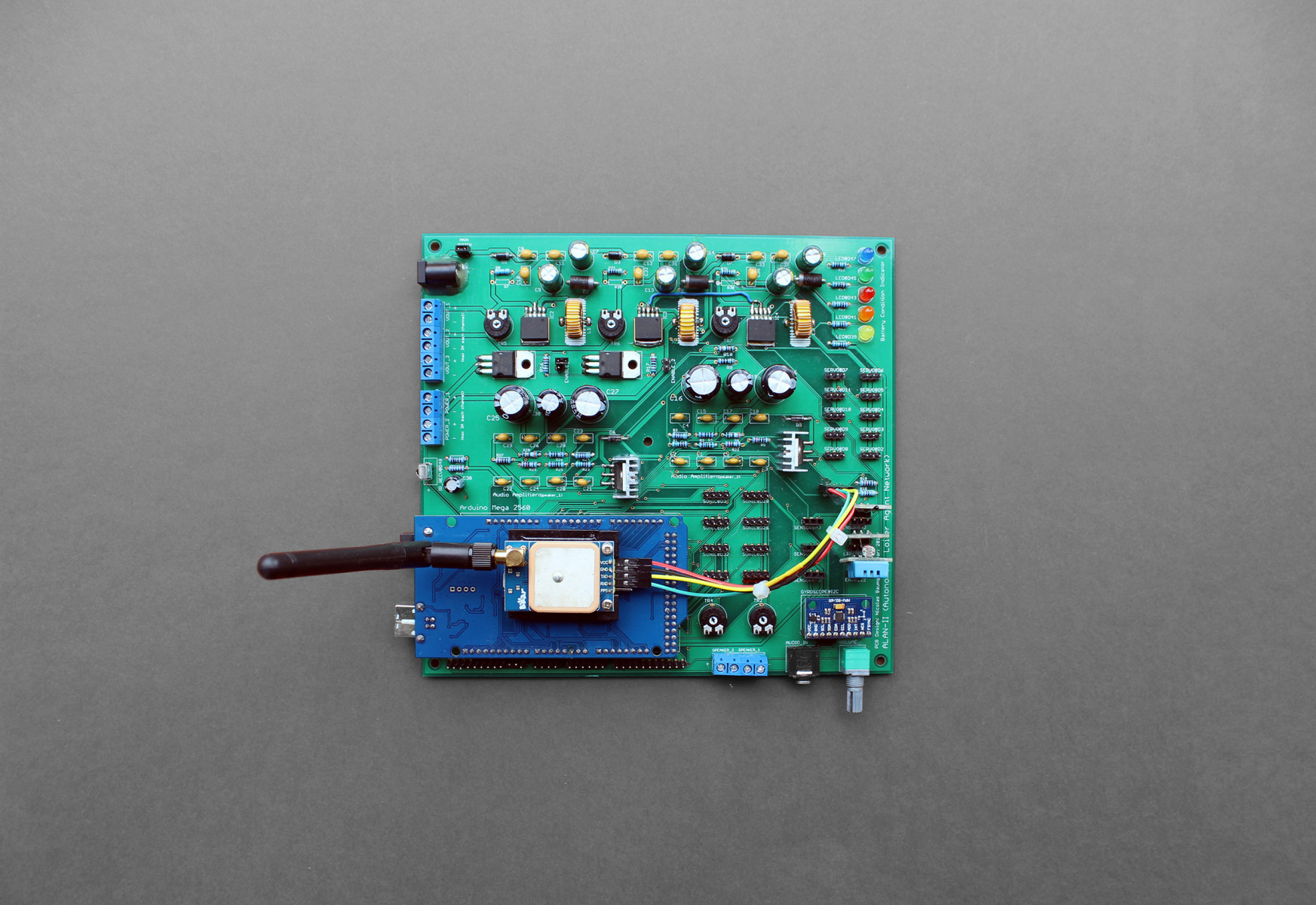
The prototype controller illustrated on the following pictures has the following features:
- ATMega 2560 Microcontroller (CPU 16Mhz, 8kB SRAM , 54x GPIOs, 16x Analog Inputs, 4x UART, I2C, SPI)
- 3x DC/DC Buck Converter Step Down Modules (LM2596 , max. 3A each)
- 2x High Power Outputs Controlled by ATMega 2560, Adjustable Voltage (BD239, max. 3A each)
- 1x Stereo Audio Amplifier (TDA2003, 12V, 10W)
- 12x Servo Motor Outputs
- 8x Proximity Sensor Inputs
- 6x Generic Sensor Inputs (Temperature, Humidity, Light, etc.)
- 5x Indicator LEDs
- 1x Gyroscope + Accelerometer
- 1x GPS Module
- 1x Infrared Receiver
- 1x Battery Voltage Meter
The current prototype is manufactured in Through Hole Technology (THT), the final revision will be made from Surface Mounted Devices (SMD) for a smaller form factor.
Software
The software of the system presented here is divided into three parts. This section focuses on the Remote Controller application. The agent itself, consisting of the Low Level Controller and the High Level Controller, periodically broadcasts UDP beacon datagrams containing its dynamically assigned IP address and a fixed port number. Presumed that the Remote Controller computer is connected to the same sub network, these broadcasted UDP beacon datagrams let’s the Remote Controller automatically detect agents by decoding the packets containing the agent’s IP address. As soon as a robot is found, a bi-directional TCP/IP connection is established for getting sensory data from the agent and for sending commands to the agent. In parallel, a second, uni-directional connection is established to transmit real-time video data from the agent to the user.
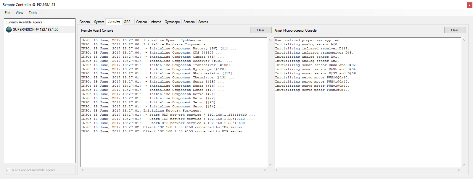
The screenshots in the gallery below illustrate the functionality of the Remote Controller application. Mostly network related statistical information is found on the General tab. Round trip times that measures the time a packet takes from the Remote Controller -> High Level Commander -> Low Level Commander and back again. These packets are also used to check the vitality of all communication links across the entire system. In case any link goes off-line, motors and other crucial or dangerous system parts will be shut-down immediately.
The System tab gives an overview of all installed system components, such as CPU, GPU, RAM, disk drives, sensors, actors and network- and battery states. This panel is also used for adding new sensors and actors. Components can be configured by double-clicking (cp. screenshots for details).
The Console tab shows debug output of the High Level Controller and Low Level Controller which are redirected to the Remote Controller. In the next tab, GPS data is visualized on a map. The Camera tab show the real-time video stream of the installed cameras. Video resolution and encoding quality can be configured.
The Servo tab(s), mainly named by their function, lets you experiment with the motors, either controlled by the mouse or by using a joystick respectively a game pad. Servos need to be configured first with their respective minimal and maximal PWM width. Subsequently, the Servo Action Library window can be used to design entire movement sequences. These sequences can be bundled together to Servo Actions which then can be triggered when certain conditions are given (e.g. a sensor threshold or voice command). Finally, an integrated Speech Synthesizer translates text to speech which can also be triggered by any auto- or user-defined condition.
Usage Example
In this section I proudly present an instance of the infamous Hollywood robot Wall-E built by a good friend of mine, Steven from www.roboterbau.ch. The Multipurpose Robot Controller meets the requirements for controlling Wall-E perfectly.

The following videos show an excerpt of Wall-E’s functionality.


